

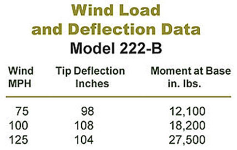
Description
|
Model 222B Impedance Chart |
||
|
Frequency MHz |
Resistance Ohms |
Reactance Ohms |
|
2 |
5 |
-600 |
|
3 |
7 |
-385 |
|
4 |
10 |
-245 |
|
5 |
20 |
-145 |
|
6 |
30 |
-55 |
|
7 |
60 |
25 |
|
8 |
80 |
100 |
|
9 |
135 |
180 |
|
10 |
225 |
270 |
|
11 |
410 |
370 |
|
12 |
775 |
250 |
|
13 |
900 |
-250 |
|
14 |
465 |
-470 |
|
15 |
251 |
-400 |
|
16 |
125 |
-225 |
|
17 |
85 |
-175 |
|
18 |
65 |
-105 |
|
19 |
60 |
-62 |
|
20 |
65 |
25 |
|
22 |
110 |
14 |
|
24 |
250 |
250 |
|
26 |
545 |
140 |
|
28 |
450 |
-240 |
|
30 |
135 |
-165 |
|
Measured over a ground plane of 12 ground radials of 0.12” ga. Copper wire equally spaced around the center and grounded at the antenna base. NOTE: When installing the Model 222B in fixed station applications, a ground plane should be provided beneath the antenna. |
||
Reviews
There are no reviews yet.